

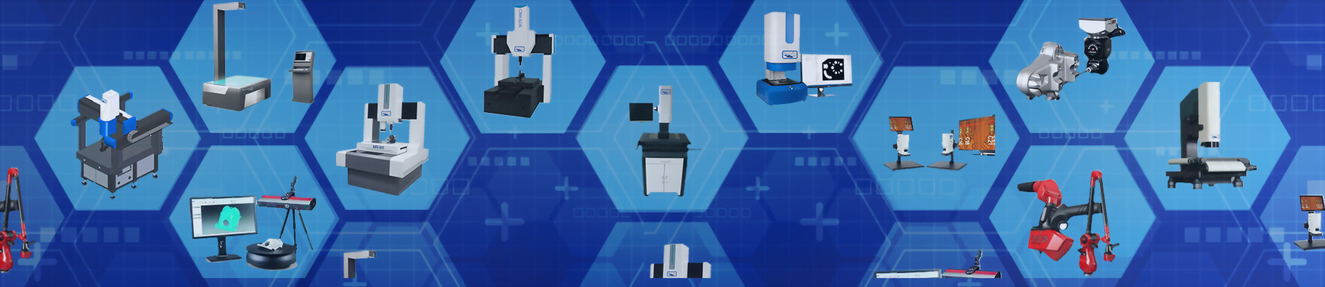

What is a 3D Measuring Instrument? Working Principles & Selection Guide
What is a 3D Measuring Instrument? Working Principles & Selection Guide
In modern precision manufacturing and quality control (QC), product geometries are becoming increasingly complex. Traditional tools like vernier calipers, micrometers, or single-point touch probes are hitting their limits in terms of efficiency and comprehensive data capture.
This is where a 3D measuring instrument (also referred to as a 3D measuring system or 3D metrology tool) comes into play.
Put simply, what is a 3D measuring instrument? It is a digital device that captures the three-dimensional spatial coordinates (X, Y, and Z axes) of an object's surface using optical, laser, or tactile probing technologies. Unlike traditional tools that measure only a single dimension at a time, a 3D measuring device brings the entire physical part into a digital space, creating a complete 3D model where every minute detail and deviation is visible.
Table of Contents
-
Traditional Measurement vs. 3D Measurement: Why Upgrade?
-
Standard Workflow of a 3D Measuring Instrument
-
Types of 3D Measuring Instruments and Their Applications
-
Frequently Asked Questions (FAQ)
Traditional Measurement vs. 3D Measurement: Why Upgrade?
A common question among QA engineers is: "We are used to our 2D optical comparators and calipers; why switch to 3D?"
The answer comes down to efficiency and completeness.
When dealing with complex freeform surfaces (such as automotive body panels or turbine blades) or deep features, 2D inspection only provides a partial view. A 3D measuring instrument, however, delivers full-dimensional inspection. It allows you to compare the scanned data directly against the original 3D CAD model, using color maps to instantly pinpoint areas of deformation or thickness variations.
Standard Workflow of a 3D Measuring Instrument
Regardless of whether you use an optical or laser-based 3D measuring instrument, the standard inspection process generally involves the following four steps:
-
Part Setup & Preparation: Place the target part on the measurement platform. Depending on the technology, apply positioning targets (markers) or adjust the ambient lighting conditions.
-
3D Scanning & Data Capture: Activate the 3D measuring instrument. The non-contact laser or structured light swiftly captures the surface, generating millions of spatial coordinate points.
-
Point Cloud Processing & CAD Comparison: Import the acquired "Point Cloud" data into the inspection software and precisely align it with the nominal 3D CAD design file.
-
Automated Inspection Reporting: The software automatically computes geometric dimensioning and tolerancing (GD&T) along with full-scale deviations, generating a comprehensive graphical inspection report with a single click.
Types of 3D Measuring Instruments and Their Applications
Different manufacturing processes require different 3D metrology approaches. Here is a comparison of the mainstream technologies available:
| Technology Category | Working Principle | Core Advantage | Best Application Scenarios |
| Blue Light / Structured Light 3D Measuring | Projects structured light patterns; cameras capture the distortion to calculate depth. | Extremely fast, high point density, excellent detail resolution. | Automotive components, mold inspection, reverse engineering, complex freeform surfaces. |
| Laser Line / Line Laser Scanning | Uses a laser line projection to measure surface deviations. | Low sensitivity to ambient light, excellent for large-scale objects. | Large castings, sheet metal parts, welded structures. |
| Tactile Probing / Contact 3D Measuring | Uses a physical probe to contact specific points on the workpiece. | Highest accuracy, completely unaffected by surface color or reflectivity. | High-precision machined parts, prismatic components, geometric tolerance verification. |
Frequently Asked Questions
Q1: What is the difference between a 3D measuring instrument and a traditional 2D vision measuring machine?
A 2D vision system primarily handles planar (X and Y axes) geometric dimensions and image contrasts, making it ideal for flat parts or single-plane inspections. A 3D measuring instrument, on the other hand, adds Z-axis height and depth data, allowing it to inspect complex three-dimensional surfaces, steps, volumes, and 3D GD&T for comprehensive spatial analysis.
Q2: Can highly reflective or pitch-black parts be measured using 3D measuring systems?
Yes. Although traditional optical scanning can be challenged by shiny or light-absorbing surfaces, modern advanced 3D measuring instruments overcome this. By utilizing blue light technology, adjusting exposure parameters, or applying a light coating of eco-friendly vanishing spray, they easily capture highly reflective metals or dark plastics.
Q3: What is reverse engineering, and how does a 3D measuring device fit into it?
Reverse engineering is the process of replicating or modifying an existing part when the original 3D CAD drawings are unavailable. Through 3D measuring, you can quickly and accurately capture the physical object's surface geometry as a point cloud. This data is then converted into a usable 3D model (such as STL or STEP files) for CAD modification, 3D printing, or CNC machining.
Q4: Can 3D measuring be integrated into fully automated in-line inspection?
Absolutely. Modern 3D measuring systems can be integrated with industrial robotic arms and automated production lines. As soon as a part arrives at the station, it triggers automated scanning, real-time CAD comparison, and OK/NG judgment without human intervention—making it a core technology for smart manufacturing and Industry 4.0.
